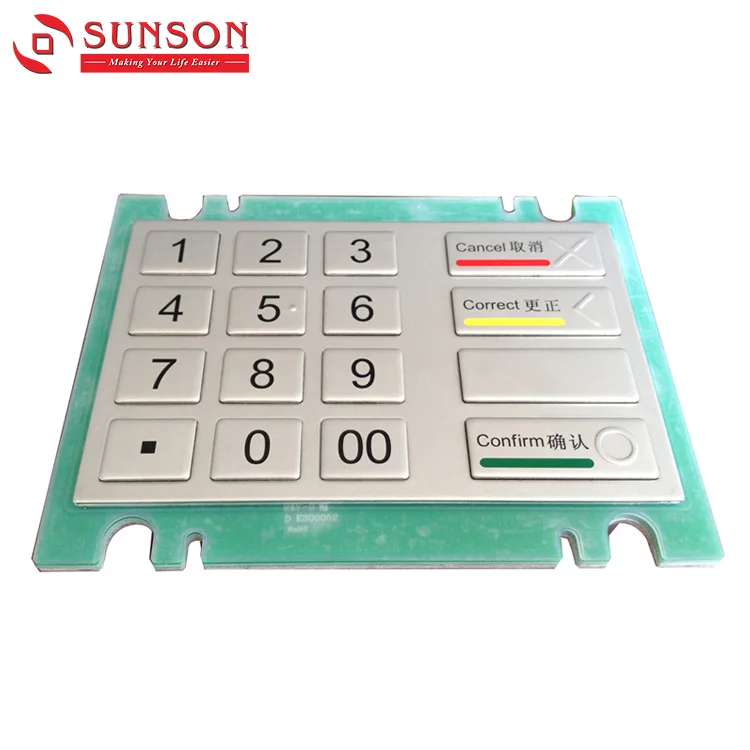
The controller can also be programmed to interpret the key input as data or a command. As such, the key that’s pressed can be identified.

Each row is set to HIGH, one after the other, and the digital input of all of the columns is polled.Īs each button is connected to only one row and one column, if a button is pressed, the logical signal (which is HIGH in this example) will be detected, but for only one of the columns. The controller is, then, programmed such that the keypad operates as active-HIGH. Now, let’s suppose the row pins are set to the digital output and the column pins are set as a digital input. The keypad can operate active-HIGH or active-LOW. The row pins are set as digital output and the column pins are set as digital input or vice versa.
#PIN KEYPAD LAYOUT SERIES#
This is done by interfacing all of the row and column terminals with the microcontroller pins via current-limiting resistors, which are connected in a series - between each terminal and the respective controller pin. To detect a matrix keypad’s input, the rows and columns must be interfaced with the microcontroller. This is a circuit diagram of a 4×4 membrane keypad:Įach push button in the matrix keypad is connected to only one row and one column. A 4×3 matrix keypad has four rows and three columns, and a 4×1 matrix keypad has four rows and one column. A 4×4 matrix keypad has four rows and four columns. Membrane keypads are now available and come in sizes 4×4, 4×3, 4×2, 4×1, and others. Each push-button is connected to only one row and only one column. These keypads are designed by multiplexing push buttons into rows and columns, which form a matrix of push buttons. However, these types of keypads required many pins to interface with a controller/computer and the only way the key input could be detected was polling by the microcontroller/microprocessor.įor a long time, matrix keypads have been a popular human interface component for embedded systems. There was a time when matrix keypads, designed by multiplexing push buttons, were typically used as keypads. In this case, an “input device” refers to a component used to input data or commands by the user. Keypads are the most common input devices used in embedded systems. Interestingly, it can be interfaced with a microcontroller or Arduino by using only two pins. The TTP229 is a popular, 4×4 keypad that supports 8/16 key inputs with single and multi-key options. In this tutorial, we’ll interface an input device - specifically, a TTP229 capacitive touch keypad - with Arduino. Embedded systems are built by interfacing several input and output devices with a controller or computer. A buzzer is an audio signaling output device.
#PIN KEYPAD LAYOUT HOW TO#
In the previous tutorial, we learned how to interface a buzzer with Arduino.


 0 kommentar(er)
